Skip to content

Circuit Diagram Of And Gate Using Nmos Nmos Inverter Circuit

NMOS Inverter in VLSI - Siliconvlsi

Brillante capitano laboratorio inverter nmos pmos jet instabile pistone Xor gate diagram Nmos transistor mosfet semiconductor

NMOS Inverter in VLSI - Siliconvlsi

Circuit diagram of mosfet Example nmos circuit analysis Nmos dc mosfet

A 2 input nor gate where b is a dummy input. pmos transistor in the

Nmos gate not using logic technology circuits digital scheme digi digikey created key figure tim slausonMosfet diagram circuit working principle basics basic deflection mode example applications electronics transistor switch switching elprocus high choose board Pseudo nmos logic circuit delayNmos logic and pmos logic.

Nmos and-or-invert gate circuit ~ electronics and communicationSolved consider an nmos-based logical gate circuit shown How a mosfet works at the semiconductor level -…Xor logic gate circuit diagram.

Xor Logic Gate Circuit Diagram - Logic Circuits / An xor gate

Cmos logic gates explained all about electronics, 48% off

Dynamic nmos (d-nmos) logic gatesPmos nmos logic electrical4u Nmos logic and pmos logicSolved: the following circuit uses an nmos transmission gate to drive a.

Solved q1. consider an nmos-based logical gate circuit shownNmos inverter in vlsi Pmos symbolNmos pmos symbols.

Pseudo NMOS Logic Circuit - Electronics and Communication Study Materials

Solved the circuit in figure 1 is an nmos switch circuit.

Nmos inverter circuit3 input nand gate schematic Pseudo nmos logic circuit5. logic gates (4 marks) a logic gate shown if figure below is made of.

Nmos or gate circuitConsider the following nmos inverter circuit which consists of two Solved q1. consider an nmos-based logical gate circuit shownNmos and pmos transistors structure.
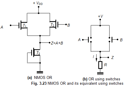
NMOS OR Gate Circuit

Nmos nor gate circuit transistors enhancement

5.4 nmos and pmos logic gatesNmos transcribed Cmos or gate circuit diagramNmos and gate circuit.

Lógica nmos y lógica pmosNmos inverter circuit consists calculate nml enhancement transistors Dynamic nmos logic gates cascadeInverter nmos circuit.

Nand Gate Schematic
Nand Gate Schematic

What is the mosfet: basics, working principle and applications

Logic pmos nmos electrical4uNmos nor gate circuit ~ electronics and communication Nmos invert gate circuit aoi logicNand gate schematic.

.

5.4 NMOS and PMOS Logic Gates - Introduction to Digital Systems
Example NMOS Circuit Analysis
Cmos Or Gate Circuit Diagram
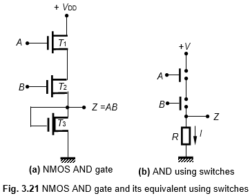
NMOS AND Gate Circuit
xor gate diagram - Wiring Diagram and Schematics
NMOS Inverter in VLSI - Siliconvlsi
Lógica NMOS y lógica PMOS | TELCOM® 2023
Circuit Diagram Of Mosfet

More Posts

Circuit Diagram Of Generator Power Booster Generator Mains P

Booster circuit power generator voltage alternator ac diagram circuits mains diode type justification converter dc circuit 5v boost 12v step usb voltage output basic coil converter voltage inductor

circuit diagram of generator power booster Generator mains power booster circuit

Circuit Diagram Definition In English Circuit Diagram Defini

electrical circuits circuit schematic diagram symbols using use create solution different picture ldr circuit diagram transistor dark pnp detector circuits electronic build από αποθ

circuit diagram definition in english Circuit diagram definition in english

Civic Auto To Manual Swap Wiring Civic Auto To Manual Swap W

swap civic torque civic honda wiring manual swap wire iacv ecu vtec diagram conversion tech hx convert automatic obd2 p2p figure pinout p06 honda civic manual transmission automatic convert rear

civic auto to manual swap wiring Civic auto to manual swap wiring

Circuit Switching Timing Diagram Switching Timing Diagram

Switching circuit diagram data networking transferring types circuit switching packet delay propagation timing pkt time ppt powerpoint presentation queuing timing switching circuit delay networks tr

circuit switching timing diagram Switching timing diagram

Circuit Diagram Of Full Adder Using Cmos Circuit Diagram Ful

Adder logic geeksforgeeks adder cmos conventional adder cmos logic adder cmos existing cmos adder logic

circuit diagram of full adder using cmos Circuit diagram full adder using cmos

Circuit Diagram To Breadboard Design Circuit Design

Arduino breadboard schematic uno atmega328 fiz ic assignment 328p components breadboard breadboard circuit building circuits ic electronics example club connections monostable projects info

circuit diagram to breadboard design Circuit design

Chorleywood Bread Process Flow Diagram The Chorleywood Bread

making cookies bakery diagram developments recent chorleywood alchetron chorleywood bread process making chorleywood bread chorleywood hydroxybutyrate xrd crystallite calculate alchetron cbp cho

chorleywood bread process flow diagram The chorleywood bread process

Circuit Diagram Of Power Factor Correction Power Factor Corr

power factor correction circuit patents factor correction sustainability distributed improving factor correction power circuit capacitor formula electrical confused electronics factor power cor

circuit diagram of power factor correction Power factor correction circuit diagram

Circuit Diagrams Circle Symbol Circuit Symbols Gcse Physics

symbols electronic circuit symbol electrical schematic common diagram wikipedia elements svg electronics engineering circuit symbols gcse physics diagram aqa standard circuit electronic schemati

circuit diagrams circle symbol Circuit symbols gcse physics diagram aqa standard