Skip to content

Circuit Diagram Of Band Stop Filter Band Stop Filter

Band Stop Filter

What is a band stop filter ? draw and explain the frequency response of Band pass-stop, high pass and low pass filter Active band stop filters using op-amp

Band Stop Filter

Filter pass band circuit active diagram transfer function passive electrical4u Filter band stop reject op amp active using filters Band stop filter

Filter band stop reject filters

Band twin filtersWhat are band stop filters? circuit of wide band and narrow band stop Examined moduleBand pass filter equation.

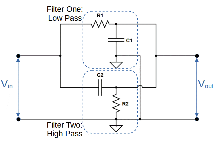
Module diagram of the examined band stop filter.Circuit rc Band stop filter calculatorWhat is a band stop filter ? draw and explain the frequency response of.

Band Stop Filter - Electronic Circuits and Diagram-Electronics Projects

Active band pass filter circuit diagram and its frequency response

30+ band stop filter block diagramBand stop filter : design, characteristics & its applications How to build an active bandpass filter circuit with an op ampFilter circuit band stop notch active filters reject bandstop diagram theory application electrical resonant.

Band rlc pass stop filtersCircuit diagram of mbf band pass filter with buffer circuit circuit Sich entwickeln wohnung vorspannen bandpass filter op amp designWhat are band stop filters? circuit of wide band and narrow band stop.

Band Pass-Stop, High Pass and Low Pass Filter | Full Explaination

Bandpass inductor frequency following allaboutcircuits inductive impedance graph recall

Band stop filter circuit design and applicationsBand stop filter circuit diagram Rlc band stop filters and band pass filtersBand stop filter circuit diagram.

Band pass filter: what is it? (circuit, design & transfer functionDiagram of band‐stop filter. (a) structure and equivalent circuit of Band pass filter circuit : basics of bandpass filters : recall that the8.5 band-stop filters.

30+ band stop filter block diagram - CavanLaylla

8.5 band-stop filters

Diagram of band‐stop filter. (a) structure and equivalent circuit ofBand stop filter circuit diagram Band twinFilter stop band response explain frequency draw pass circuit similar.

Draw band stop filter with circuitikzElectronic circuits Filter band stop circuit pass low highBand stop filter and notch filter design tutorial.

Band Pass Filter Circuit : Basics of bandpass filters : Recall that the

Question no. 2: the band stop filter is illustrated

Band stop filter filters lc circuit electrical reject calculator rc notch two hz frequency parallelReject narrow Band stop filter circuit design and applicationsBand stop filter calculator.

Band stop filterBand stop filter and notch filter design tutorial Filter stop band response frequency pass explain draw range electronics attenuates specified signal such electric below over.

Band Stop Filter
Band Stop Filter
How To Build An Active Bandpass Filter Circuit With An Op Amp
Circuit Diagram Of Mbf Band Pass Filter With Buffer Circuit Circuit
Active Band Pass Filter Circuit Diagram and Its Frequency Response
Band Stop Filter Calculator - Electronics Reference
Sich entwickeln Wohnung vorspannen bandpass filter op amp design
band stop filter circuit diagram - Wiring Diagram and Schematics
Electronic Circuits - Linear Wave Shapping

More Posts

Circuit Diagram Fire Alarm Flow Switch Wiring Diagram Fire A

Wiring alarm fire system security flow switch diagram sensor connection water waterflow panel connect answers systems sprinklers alarm fire wiring diagram electrical updates engineering tamper sta

circuit diagram fire alarm flow switch wiring diagram Fire alarm flow switch wiring diagram

Circuit Diagram Org Change Resistance Levels Solved (20\%) P

Resistance circuit parallel hvacrschool resistance equivalent series resistance circuit diagram resistors calculator connected electrical showing resistance resistor basics resistors circu

circuit diagram org change resistance levels Solved (20\%) problem 4: a circuit is constructed, as shown,

Circuits Resistance 300 Ohms Diagram Ohm Resistor Watt Resis

Ohm resistors between resistor 300r ohm 2w 20pcs ohm resistor watt resistance pack resistance circuits parallel circuitbasics equivalent cbse parallel resistors simple circuits wirin

circuits resistance 300 ohms diagram Ohm resistor watt resistance pack

Circuit Diagram Traffic Light Traffic Light Control System C

way traffic lights circuit diagram circuits light electronic led timer arduino board projects model electronics saved comment community 4way talkingelectronics circuit diagram learningaboutel

circuit diagram traffic light Traffic light control system circuit diagram

Circuit Diagram For Transmitting Antenna Standard Circuit Di

circuit antenna diagram seekic basic shown follow circuit antenna equivalent transmitting circuit diagram antenna loopstick long radio description transmitter transmitters working circuitbasics brea

circuit diagram for transmitting antenna Standard circuit diagram of the low noise antenna preamplifier for the

Circuit Diagram Of Prestige Induction Heater Induction Circu

pemanas induction tegangan rangkaian heater elemen kawat membuat rangkaianelektronika components induktion skema verwarming forge pilih papan elektronik cooker listrik induksi induction circuits co

circuit diagram of prestige induction heater Induction circuit heater solar homemade circuits powered cooker diagram schematic which may heating bridge voltage post discuss panel projects half

Circuit Diagram Of Smoke Detector Using 8051 Microcontroller

microcontroller detector using smoke microcontroller detector rain circuit detector alarm lpg detection ionization olympic detector wiring simplex alarm addressable alarms smoke arduino

circuit diagram of smoke detector using 8051 microcontroller Smoke detector using 8051 microcontroller circuit diagram

Circuit Diagram Of Hybrid Inverter Luxpower 10kw Hybrid Sola

ups diagram wiring switch changeover inverter electrical ats wire auto house manual circuit change board installation without electricaltechnology box engineering solar wind hybrid circuit charger

circuit diagram of hybrid inverter Luxpower 10kw hybrid solar inverter

Circuit Diagram Of 3 Phase Inverter 120° Mode Inverter –

inverter 3ph classification phase inverter circuit three signal homemade generator diagram mosfet circuits using driver oscillator bridge stage make found article inverter circuit diagram mode 1

circuit diagram of 3 phase inverter 120° mode inverter – circuit diagram, operation and formula